
Traffic Control for Bicycle Facilities
Section 9B.01 Application and Placement of Signs
Standard:
01 Bicycle signs shall be standard in shape, legend, and color.
02 All signs shall be retroreflectorized for use on bikeways, including shared-use paths and bicycle lane facilities.
03 Where signs serve both bicyclists and other road users, vertical mounting height and lateral placement shall be as provided in Part 2.
04 Where used on a shared-use path, no portion of a sign or its support shall be placed less than 2 feet laterally from the near edge of the path, or less than 8 feet vertically over the entire width of the shared-use path (see Figure 9B-1).
Figure 9B-1 Sign Placement on Shared-Use Paths
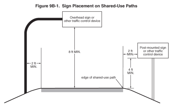
05 Mounting height for post-mounted signs on shared-use paths shall be a minimum of 4 feet, measured vertically from the bottom of the sign to the elevation of the near edge of the path surface (see Figure 9B-1).
Guidance:
06 Signs for the exclusive use of bicyclists should be located so that other road users are not confused by them.
07 The clearance for overhead signs on shared-use paths should be adjusted when appropriate to accommodate path users requiring more clearance, such as equestrians, or typical maintenance or emergency vehicles.
Section 9B.02 Design of Bicycle Signs
Standard:
01 If the sign or plaque applies to motorists and bicyclists, then the size shall be as shown for conventional roads in Tables 2B-1, 2C-2, or 2D-1.
02 The minimum sign and plaque sizes for shared-use paths shall be those shown in Table 9B-1, and shall be used only for signs and plaques installed specifically for bicycle traffic applications. The minimum sign and plaque sizes for bicycle facilities shall not be used for signs or plaques that are placed in a location that would have any application to other vehicles.
| Sign or Plaque | Sign Designation | Section | Shared-Use Path | Roadway |
|---|---|---|---|---|
| Stop | R1-1 | 2B.05, 9B.03 | 18 x 18 | 30 x 30 |
| Yield | R1-2 | 2B.08, 9B.03 | 18 x 18 x 18 | 30 x 30 x 30 |
| Bike Lane | R3-17 | 9B.04 | — | 24 x 18 |
| Bike Lane (plaques) | R3-17aP, R3-17bP | 9B.04 | — | 24 x 8 |
| Movement Restriction | R4-1,2,3,7,16 | 2B.28,29,30,32; 9B.14 | 12 x 18 | 18 x 24 |
| Begin Right Turn Lane Yield to Bikes | R4-4 | 9B.05 | — | 36 x 30 |
| Bicycles May Use Full Lane | R4-11 | 9B.06 | — | 30 x 30 |
| Bicycle Wrong Way | R5-1b | 9B.07 | 12 x 18 | 12 x 18 |
| No Motor Vehicles | R5-3 | 9B.08 | 24 x 24 | 24 x 24 |
| No Bicycles | R5-6 | 9B.09 | 18 x 18 | 24 x 24 |
| No Parking Bike Lane | R7-9,9a | 9B.10 | — | 12 x 18 |
| No Pedestrians | R9-3 | 9B.09 | 18 x 18 | 18 x 18 |
| Ride With Traffic (plaque) | R9-3cP | 9B.07 | 12 x 12 | 12 x 12 |
| Bicycle Regulatory | R9-5,6 | 9B.11 | 12 x 18 | 12 x 18 |
| Shared-Use Path Restriction | R9-7 | 9B.12 | 12 x 18 | — |
| No Skaters | R9-13 | 9B.09 | 18 x 18 | 18 x 18 |
| No Equestrians | R9-14 | 9B.09 | 18 x 18 | 18 x 18 |
| Push Button for Green Light | R10-4 | 9B.11 | 9 x 12 | 9 x 12 |
| To Request Green Wait on Symbol | R10-22 | 9B.13 | 12 x 18 | 12 x 18 |
| Bike Push Button for Green Light | R10-24 | 9B.11 | 9 x 15 | 9 x 15 |
| Push Button to Turn On Warning Lights | R10-25 | 9B.11 | 9 x 12 | 9 x 12 |
| Bike Push Button for Green Light (arrow) | R10-26 | 9B.11 | 9 x 15 | 9 x 15 |
| Grade Crossing (Crossbuck) | R15-1 | 8B.03, 9B.14 | 24 x 4.5 | 48 x 9 |
| Number of Tracks (plaque) | R15-2P | 8B.03, 9B.14 | 13.5 x 9 | 27 x 18 |
| Look | R15-8 | 8B.17, 9B.14 | 18 x 9 | 36 x 18 |
| Turn and Curve Warning | W1-1,2,3,4,5 | 2C.04, 9B.15 | 18 x 18 | 24 x 24 |
| Arrow Warning | W1-6,7 | 2C.12, 2C.47, 9B.15 | 24 x 12 | 36 x 18 |
| Intersection Warning | W2-1,2,3,4,5 | 2C.46, 9B.16 | 18 x 18 | 24 x 24 |
| Stop,Yield, Signal Ahead | W3-1,2,3 | 2C.36, 9B.19 | 18 x 18 | 30 x 30 |
| Narrow Bridge | W5-2 | 2C.20, 9B.19 | 18 x 18 | 30 x 30 |
| Path Narrows | W5-4a | 9B.19 | 18 x 18 | — |
| Hill | W7-5 | 9B.19 | 18 x 18 | 30 x 30 |
| Bump or Dip | W8-1,2 | 2C.28, 9B.17 | 18 x 18 | 24 x 24 |
| Pavement Ends | W8-3 | 2C.30, 9B.17 | 18 x 18 | 30 x 30 |
| Bicycle Surface Condition | W8-10 | 9B.17 | 18 x 18 | 30 x 30 |
| Slippery When Wet (plaque) | W8-10P | 9B.17 | 12 x 9 | 12 x 9 |
| Grade Crossing Advance Warning | W10-1 | 8B.06, 9B.19 | 24 Dia. | 36 Dia. |
| No Train Horn (plaque) | W10-9P | 8B.21, 9B.19 | 18 x 12 | 30 x 24 |
| Skewed Crossing | W10-12 | 8B.25, 9B.19 | 18 x 18 | 36 x 36 |
| Bicycle Warning | W11-1 | 9B.18 | 18 x 18 | 24 x 24 |
| Pedestrian Crossing | W11-2 | 2C.50, 9B.19 | 18 x 18 | 24 x 24 |
| Combination Bike and Ped Crossing | W11-15 | 9B.18 | 18 x 18 | 30 x 30 |
| Trail Crossing (plaque) | W11-15P | 9B.18 | 18 x 12 | 24 x 18 |
| Low Clearance | W12-2 | 2C.27, 9B.19 | 18 x 18 | 30 x 30 |
| Playground | W15-1 | 2C.51, 9B.19 | 18 x 18 | 24 x 24 |
| Share the Road (plaque) | W16-1P | 2C.60, 9B.19 | — | 18 x 24 |
| XX Feet (plaque) | W16-2P | 2C.55, 9B.18 | 18 x 12 | 24 x 18 |
| XX Ft (plaque) | W16-2aP | 2C.55, 9B.18 | 18 x 9 | 24 x 12 |
| Diagonal Arrow (plaque) | W16-7P | 9B.18 | — | 24 x 12 |
| Ahead (plaque) | W16-9P | 9B.18 | — | 24 x 12 |
| Destination (1 line) | D1-1, D1-1a | 2D.37, 9B.20 | varies x 6 | varies x 18 |
| Bicycle Destination (1 line) | D1-1b, D1-1c | 9B.20 | varies x 6 | varies x 6 |
| Destination (2 lines) | D1-2, D1-2a | 2D.37, 9B.20 | varies x 12 | varies x 30 |
| Bicycle Destination (2 lines) | D1-2b, D1-2c | 9B.20 | varies x 12 | varies x 12 |
| Destination (3 lines) | D1-3, D1-3a | 2D.37, 9B.20 | varies x 18 | varies x 42 |
| Bicycle Destination (3 lines) | D1-3b, D1-3c | 9B.20 | varies x 18 | varies x 18 |
| Street Name | D3-1 | 2D.43, 9B.20 | varies x 6 | varies x 8 |
| Bicycle Parking Area | D4-3 | 9B.23 | 12 x 18 | 12 x 18 |
| Reference Location (1-digit) | D10-1 | 2H.02, 9B.24 | 6 x 12 | 10 x 18 |
| Intermediate Reference Location (1-digit) | D10-1a | 2H.02, 9B.24 | 6 x 18 | 10 x 27 |
| Reference Location (2-digit) | D10-2 | 2H.02, 9B.24 | 6 x 18 | 10 x 27 |
| Intermediate Reference Location (2-digit) | D10-2a | 2H.02, 9B.24 | 6 x 24 | 10 x 36 |
| Reference Location (3-digit) | D10-3 | 2H.02, 9B.24 | 6 x 24 | 10 x 36 |
| Intermediate Reference Location (3-digit) | D10-3a | 2H.02, 9B.24 | 6 x 30 | 10 x 48 |
| Bike Route | D11-1, D11-1c | 9B.20 | 24 x 18 | 24 x 18 |
| Bicycles Permitted | D11-1a | 9B.25 | 18 x 18 | — |
| Bike Route (plaque) | D11-1bP | 9B.25 | 18 x 6 | — |
| Pedestrians Permitted | D11-2 | 9B.25 | 18 x 18 | — |
| Skaters Permitted | D11-3 | 9B.25 | 18 x 18 | — |
| Equestrians Permitted | D11-4 | 9B.25 | 18 x 18 | — |
| Bicycle Route | M1-8, M1-8a | 9B.21 | 12 x 18 | 18 x 24 |
| U.S. Bicycle Route | M1-9 | 9B.21 | 12 x 18 | 18 x 24 |
| Bicycle Route Auxiliary Signs | M2-1; M3-1,2,3,4; M4-1,1a,2,3,5,6,7,7a,8,14 | 9B.22 | 12 x 6 | 12 x 6 |
| Bicycle Route Arrow Signs | M5-1,2; M6-1,2,3,4,5,6,7 | 9B.22 | 12 x 9 | 12 x 9 |
| Type 3 Object Markers | OM3-L,C,R | 2C.63, 9B.26 | 6 x 18 | 12 x 36 |
Notes:
- Larger signs may be used when appropriate.
- Dimensions are shown in inches and are shown as width x height.
Option:
03 Larger size signs and plaques may be used on bicycle facilities when appropriate (see Section 2A.11).
Guidance:
04 Except for size, the design of signs and plaques for bicycle facilities should be identical to that provided in this Manual for signs and plaques for streets and highways.
Support:
05 Uniformity in design of bicycle signs and plaques includes shape, color, symbols, arrows, wording, lettering, and illumination or retroreflectorization.
Section 9B.03 STOP and YIELD Signs (R1-1, R1-2)
Standard:
01 STOP (R1-1) signs (see Figure 9B-2) shall be installed on shared-use paths at points where bicyclists are required to stop.
Figure 9B-2 Regulatory Signs and Plaques for Bicycle Facilities
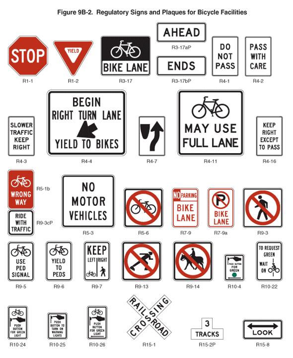
02 YIELD (R1-2) signs (see Figure 9B-2) shall be installed on shared-use paths at points where bicyclists have an adequate view of conflicting traffic as they approach the sign, and where bicyclists are required to yield the right-of-way to that conflicting traffic.
Option:
03 A 30 x 30-inch STOP sign or a 36 x 36 x 36-inch YIELD sign may be used on shared-use paths for added emphasis.
Guidance:
04 Where conditions require path users, but not roadway users, to stop or yield, the STOP or YIELD sign should be placed or shielded so that it is not readily visible to road users.
05 When placement of STOP or YIELD signs is considered, priority at a shared-use path/roadway intersection should be assigned with consideration of the following:
- Relative speeds of shared-use path and roadway users,
- Relative volumes of shared-use path and roadway traffic, and
- Relative importance of shared-use path and roadway.
06 Speed should not be the sole factor used to determine priority, as it is sometimes appropriate to give priority to a high-volume shared-use path crossing a low-volume street, or to a regional shared-use path crossing a minor collector street.
07 When priority is assigned, the least restrictive control that is appropriate should be placed on the lower priority approaches. STOP signs should not be used where YIELD signs would be acceptable.
Section 9B.04 Bike Lane Signs and Plaques (R3-17, R3-17aP, R3-17bP)
Standard:
01 The Bike Lane (R3-17) sign and the R3-17aP and R3-17bP plaques (see Figure 9B-2) shall be used only in conjunction with marked bicycle lanes as described in Section 9C.04.
Guidance:
02 If used, Bike Lane signs and plaques should be used in advance of the upstream end of the bicycle lane, at the downstream end of the bicycle lane, and at periodic intervals along the bicycle lane as determined by engineering judgment based on prevailing speed of bicycle and other traffic, block length, distances from adjacent intersections, and other considerations.
Section 9B.05 BEGIN RIGHT TURN LANE YIELD TO BIKES Sign (R4-4)
Option:
01 Where motor vehicles entering an exclusive right-turn lane must weave across bicycle traffic in bicycle lanes, the BEGIN RIGHT TURN LANE YIELD TO BIKES (R4-4) sign (see Figure 9B-2) may be used to inform both the motorist and the bicyclist of this weaving maneuver (see Figures 9C-1, 9C-4, and 9C-5).
Guidance:
02 The R4-4 sign should not be used when bicyclists need to move left because of a right-turn lane drop situation.
Section 9B.06 Bicycles May Use Full Lane Sign (R4-11)
Option:
01 The Bicycles May Use Full Lane (R4-11) sign (see Figure 9B-2) may be used on roadways where no bicycle lanes or adjacent shoulders usable by bicyclists are present and where travel lanes are too narrow for bicyclists and motor vehicles to operate side by side.
02 The Bicycles May Use Full Lane sign may be used in locations where it is important to inform road users that bicyclists might occupy the travel lane.
03 Section 9C.07 describes a Shared Lane Marking that may be used in addition to or instead of the Bicycles May Use Full Lane sign to inform road users that bicyclists might occupy the travel lane.
Support:
04 The Uniform Vehicle Code (UVC) defines a "substandard width lane" as a "lane that is too narrow for a bicycle and a vehicle to travel safely side by side within the same lane."
Section 9B.07 Bicycle Wrong Way Sign and RIDE WITH TRAFFIC Plaque (R5-1b, R9-3cP)
Option:
01 The Bicycle WRONG WAY (R5-1b) sign and RIDE WITH TRAFFIC (R9-3cP) plaque (see Figure 9B-2) may be placed facing wrong-way bicycle traffic, such as on the left side of a roadway.
02 This sign and plaque may be mounted back-to-back with other signs to minimize visibility to other traffic.
Guidance:
03 The RIDE WITH TRAFFIC plaque should be used only in conjunction with the Bicycle WRONG WAY sign, and should be mounted directly below the Bicycle WRONG WAY sign.
Section 9B.08 NO MOTOR VEHICLES Sign (R5-3)
Option:
01 The NO MOTOR VEHICLES (R5-3) sign (see Figure 9B-2) may be installed at the entrance to a shared-use path.
Section 9B.09 Selective Exclusion Signs
Option:
01 Selective Exclusion signs (see Figure 9B-2) may be installed at the entrance to a roadway or facility to notify road or facility users that designated types of traffic are excluded from using the roadway or facility.
Standard:
02 If used, Selective Exclusion signs shall clearly indicate the type of traffic that is excluded.
Support:
03 Typical exclusion messages include:
- No Bicycles (R5-6),
- No Pedestrians (R9-3),
- No Skaters (R9-13), and
- No Equestrians (R9-14).
Option:
04 Where bicyclists, pedestrians, and motor-driven cycles are all prohibited, it may be more desirable to use the R5-10a word message sign that is described in Section 2B.39.
Section 9B.10 No Parking Bike Lane Signs (R7-9, R7-9a)
Standard:
01 If the installation of signs is necessary to restrict parking, standing, or stopping in a bicycle lane, appropriate signs as described in Sections 2B.46 through 2B.48, or the No Parking Bike Lane (R7-9 or R7-9a) signs (see Figure 9B-2) shall be installed.
Section 9B.11 Bicycle Regulatory Signs (R9-5, R9-6, R10-4, R10-24, R10-25, and R10-26)
Option:
01 The R9-5 sign (see Figure 9B-2) may be used where the crossing of a street by bicyclists is controlled by pedestrian signal indications.
02 Where it is not intended for bicyclists to be controlled by pedestrian signal indications, the R10-4, R10-24, or R10-26 sign (see Figure 9B-2 and Section 2B.52) may be used.
Guidance:
03 If used, the R9-5, R10-4, R10-24, or R10-26 signs should be installed near the edge of the sidewalk in the vicinity of where bicyclists will be crossing the street.
Option:
04 If bicyclists are crossing a roadway where In-Roadway Warning Lights (see Section 4N.02) or other warning lights or beacons have been provided, the R10-25 sign (see Figure 9B-2) may be used.
05 The R9-6 sign (see Figure 9B-2) may be used where a bicyclist is required to cross or share a facility used by pedestrians and is required to yield to the pedestrians.
Section 9B.12 Shared-Use Path Restriction Sign (R9-7)
Option:
01 The Shared-Use Path Restriction (R9-7) sign (see Figure 9B-2) may be installed to supplement a solid white pavement marking line (see Section 9C.03) on facilities that are to be shared by pedestrians and bicyclists in order to provide a separate designated pavement area for each mode of travel. The symbols may be switched as appropriate.
Guidance:
02 If two-way operation is permitted on the facility for pedestrians and/or bicyclists, the designated pavement area that is provided for each two-way mode of travel should be wide enough to accommodate both directions of travel for that mode.
Section 9B.13 Bicycle Signal Actuation Sign (R10-22)
Option:
01 The Bicycle Signal Actuation (R10-22) sign (see Figure 9B-2) may be installed at signalized intersections where markings are used to indicate the location where a bicyclist is to be positioned to actuate the signal (see Section 9C.05).
Guidance:
02 If the Bicycle Signal Actuation sign is installed, it should be placed at the roadside adjacent to the marking to emphasize the connection between the marking and the sign.
Section 9B.14 Other Regulatory Signs
Option:
01 Other regulatory signs described in Chapter 2B may be installed on bicycle facilities as appropriate.
Section 9B.15 Turn or Curve Warning Signs (W1 Series)
Guidance:
01 To warn bicyclists of unexpected changes in shared-use path direction, appropriate turn or curve (W1-1 through W1-7) signs (see Figure 9B-3) should be used.
Figure 9B-3 Warning Signs and Plaques and Object Markers for Bicycle Facilities

02 The W1-1 through W1-5 signs should be installed at least 50 feet in advance of the beginning of the change of alignment.
Section 9B.16 Intersection Warning Signs (W2 Series)
Option:
01 Intersection Warning (W2-1 through W2-5) signs (see Figure 9B-3) may be used on a roadway, street, or shared-use path in advance of an intersection to indicate the presence of an intersection and the possibility of turning or entering traffic.
Guidance:
02 When engineering judgment determines that the visibility of the intersection is limited on the shared-use path approach, Intersection Warning signs should be used.
03 Intersection Warning signs should not be used where the shared-use path approach to the intersection is controlled by a STOP sign, a YIELD sign, or a traffic control signal.
Section 9B.17 Bicycle Surface Condition Warning Sign (W8-10)
Option:
01 The Bicycle Surface Condition Warning (W8-10) sign (see Figure 9B-3) may be installed where roadway or shared-use path conditions could cause a bicyclist to lose control of the bicycle.
02 Signs warning of other conditions that might be of concern to bicyclists, including BUMP (W8-1), DIP (W8-2), PAVEMENT ENDS (W8-3), and any other word message that describes conditions that are of concern to bicyclists, may also be used.
03 A supplemental plaque may be used to clarify the specific type of surface condition.
Section 9B.18 Bicycle Warning and Combined Bicycle/Pedestrian Signs (W11-1 and W11-15)
Support:
01 The Bicycle Warning (W11-1) sign (see Figure 9B-3) alerts the road user to unexpected entries into the roadway by bicyclists, and other crossing activities that might cause conflicts. These conflicts might be relatively confined, or might occur randomly over a segment of roadway.
Option:
02 The combined Bicycle/Pedestrian (W11-15) sign (see Figure 9B-3) may be used where both bicyclists and pedestrians might be crossing the roadway, such as at an intersection with a shared-use path. A TRAIL X-ING (W11-15P) supplemental plaque (see Figure 9B-3) may be mounted below the W11-15 sign.
03 A supplemental plaque with the legend AHEAD or XX FEET may be used with the Bicycle Warning or combined Bicycle/Pedestrian sign.
Guidance:
04 If used in advance of a specific crossing point, the Bicycle Warning or combined Bicycle/Pedestrian sign should be placed at a distance in advance of the crossing location that conforms with the guidance given in Table 2C-4.
Standard:
05 Bicycle Warning and combined Bicycle/Pedestrian signs, when used at the location of the crossing, shall be supplemented with a diagonal downward pointing arrow (W16-7P) plaque (see Figure 9B-3) to show the location of the crossing.
Option:
06 A fluorescent yellow-green background color with a black legend and border may be used for Bicycle Warning and combined Bicycle/Pedestrian signs and supplemental plaques.
Guidance:
07 When the fluorescent yellow-green background color is used, a systematic approach featuring one background color within a zone or area should be used. The mixing of standard yellow and fluorescent yellow-green backgrounds within a zone or area should be avoided.
Section 9B.19 Other Bicycle Warning Signs
Option:
01 Other bicycle warning signs (see Figure 9B-3) such as PATH NARROWS (W5-4a) and Hill (W7-5) may be installed on shared-use paths to warn bicyclists of conditions not readily apparent.
02 In situations where there is a need to warn motorists to watch for bicyclists traveling along the highway, the SHARE THE ROAD (W16-1P) plaque (see Figure 9B-3) may be used in conjunction with the W11-1 sign.
Guidance:
03 If used, other advance bicycle warning signs should be installed at least 50 feet in advance of the beginning of the condition.
04 Where temporary traffic control zones are present on bikeways, appropriate signs from Part 6 should be used.
Option:
05 Other warning signs described in Chapter 2C may be installed on bicycle facilities as appropriate.
Section 9B.20 Bicycle Guide Signs (D1-1b, D1-1c, D1-2b, D1-2c, D1-3b, D1-3c, D11-1, D11-1c)
Option:
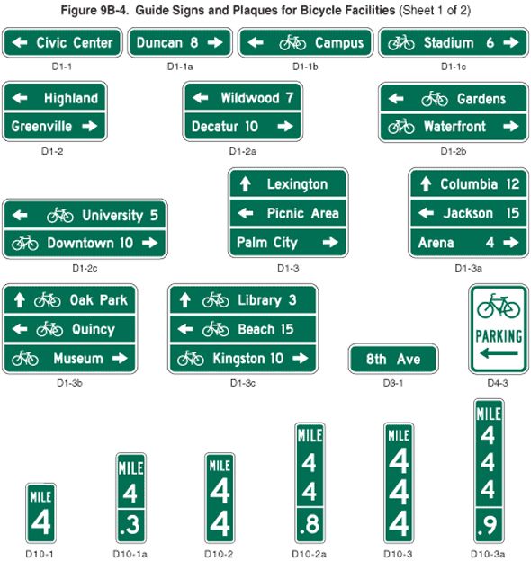
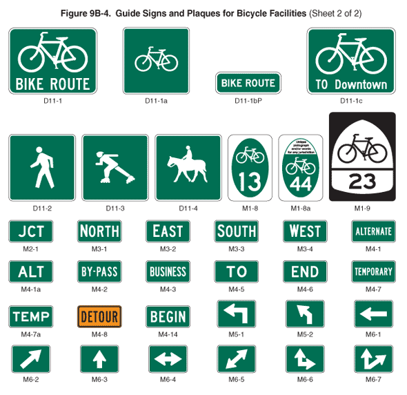
01 Bike Route Guide (D11-1) signs (see Figure 9B-4) may be provided along designated bicycle routes to inform bicyclists of bicycle route direction changes and to confirm route direction, distance, and destination.
Figure 9B-4 Guide Signs and Plaques for Bicycle Facilities
02 If used, Bike Route Guide signs may be repeated at regular intervals so that bicyclists entering from side streets will have an opportunity to know that they are on a bicycle route. Similar guide signing may be used for shared roadways with intermediate signs placed for bicyclist guidance.
03 Alternative Bike Route Guide (D11-1c) signs may be used to provide information on route direction, destination, and/or route name in place of the "BIKE ROUTE" wording on the D11-1 sign (see Figures 9B-4 and 9B-6).
04 Destination (D1-1, D1-1a) signs, Street Name (D3-1) signs, or Bicycle Destination (D1-1b, D1-1c, D1-2b, D1-2c, D1-3b, D1-3c) signs (see Figure 9B-4) may be installed to provide direction, destination, and distance information as needed for bicycle travel. If several destinations are to be shown at a single location, they may be placed on a single sign with an arrow (and the distance, if desired) for each name. If more than one destination lies in the same direction, a single arrow may be used for the destinations.
Guidance:
05 Adequate separation should be made between any destination or group of destinations in one direction and those in other directions by suitable design of the arrow, spacing of lines of legend, heavy lines entirely across the sign, or separate signs.
Standard:
06 An arrow pointing to the right, if used, shall be at the extreme right-hand side of the sign. An arrow pointing left or up, if used, shall be at the extreme left-hand side of the sign. The distance numerals, if used, shall be placed to the right of the destination names.
07 On Bicycle Destination signs, a bicycle symbol shall be placed next to each destination or group of destinations. If an arrow is at the extreme left, the bicycle symbol shall be placed to the right of the respective arrow.
Guidance:
08 Unless a sloping arrow will convey a clearer indication of the direction to be followed, the directional arrows should be horizontal or vertical.
09 The bicycle symbol should be to the left of the destination legend.
10 If several individual name signs are assembled into a group, all signs in the assembly should have the same horizontal width.
11 Because of their smaller size, Bicycle Destination signs should not be used as a substitute for vehicular destination signs when the message is also intended to be seen by motorists.
Support:
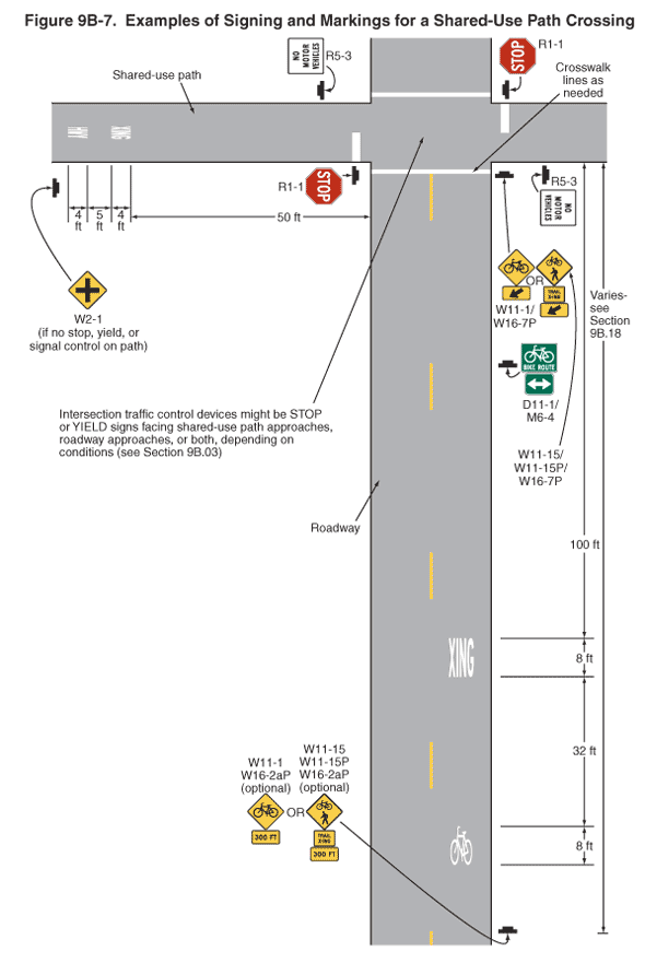
12 Figure 9B-5 shows an example of the signing for the beginning and end of a designated bicycle route on a shared-use path. Figure 9B-6 shows an example of signing for an on-roadway bicycle route. Figure 9B-7 shows examples of signing and markings for a shared-use path crossing.
Figure 9B-5 Example of Signing for the Beginning and End of a Designated Bicycle Route on a Shared-Use Path
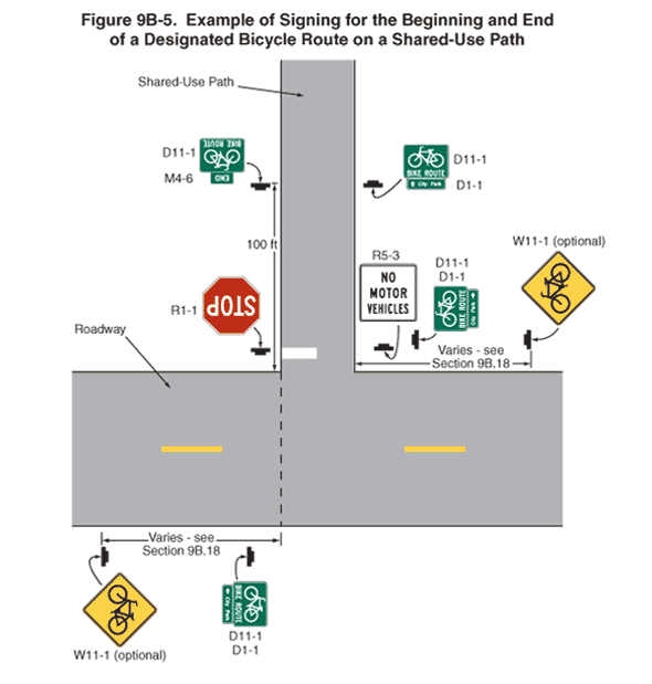
Figure 9B-6 Example of Bicycle Guide Signing
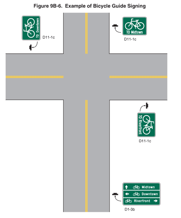
Figure 9B-7 Examples of Signing and Markings for a Shared-Use Path Crossing
Section 9B.21 Bicycle Route Signs (M1-8, M1-8a, M1-9)
Option:
01 To establish a unique identification (route designation) for a State or local bicycle route, the Bicycle Route (M1-8, M1-8a) sign (see Figure 9B-4) may be used.
Standard:
02 The Bicycle Route (M1-8) sign shall contain a route designation and shall have a green background with a retroreflectorized white legend and border. The Bicycle Route (M1-8a) sign shall contain the same information as the M1-8 sign and in addition shall include a pictograph or words that are associated with the route or with the agency that has jurisdiction over the route.
Guidance:
03 Bicycle routes, which might be a combination of various types of bikeways, should establish a continuous routing.
04 Where a designated bicycle route extends through two or more States, a coordinated submittal by the affected States for an assignment of a U.S. Bicycle Route number designation should be sent to the American Association of State Highway and Transportation Officials (see Page i for the address).
Standard:
05 The U.S. Bicycle Route (M1-9) sign (see Figure 9B-4) shall contain the route designation as assigned by AASHTO and shall have a black legend and border with a retroreflectorized white background.
Guidance:
06 If used, the Bicycle Route or U.S. Bicycle Route signs should be placed at intervals frequent enough to keep bicyclists informed of changes in route direction and to remind motorists of the presence of bicyclists.
Option:
07 Bicycle Route or U.S. Bicycle Route signs may be installed on shared roadways or on shared-use paths to provide guidance for bicyclists.
08 The Bicycle Route Guide (D11-1) sign (see Figure 9B-4) may be installed where no unique designation of routes is desired.
Section 9B.22 Bicycle Route Sign Auxiliary Plaques
Option:
01 Auxiliary plaques may be used in conjunction with Bike Route Guide signs, Bicycle Route signs, or U.S. Bicycle Route signs as needed.
Guidance:
02 If used, Junction (M2-1), Cardinal Direction (M3 series), and Alternative Route (M4 series) auxiliary plaques (see Figure 9B-4) should be mounted above the appropriate Bike Route Guide signs, Bicycle Route signs, or U.S. Bicycle Route signs.
03 If used, Advance Turn Arrow (M5 series) and Directional Arrow (M6 series) auxiliary plaques (see Figure 9B-4) should be mounted below the appropriate Bike Route Guide sign, Bicycle Route sign, or U.S. Bicycle Route sign.
04 Except for the M4-8 plaque, all route sign auxiliary plaques should match the color combination of the route sign that they supplement.
05 Route sign auxiliary plaques carrying word legends that are used on bicycle routes should have a minimum size of 12 x 6 inches. Route sign auxiliary plaques carrying arrow symbols that are used on bicycle routes should have a minimum size of 12 x 9 inches.
Option:
06 With route signs of larger sizes, auxiliary plaques may be suitably enlarged, but not such that they exceed the width of the route sign.
07 A route sign and any auxiliary plaques used with it may be combined on a single sign.
08 Destination (D1-1b and D1-1c) signs (see Figure 9B-4) may be mounted below Bike Route Guide signs, Bicycle Route signs, or U.S. Bicycle Route signs to furnish additional information, such as directional changes in the route, or intermittent distance and destination information.
Section 9B.23 Bicycle Parking Area Sign (D4-3)
Option:
01 The Bicycle Parking Area (D4-3) sign (see Figure 9B-4) may be installed where it is desirable to show the direction to a designated bicycle parking area. The arrow may be reversed as appropriate.
Standard:
02 The legend and border of the Bicycle Parking Area sign shall be green on a retroreflectorized white background.
Section 9B.24 Reference Location Signs (D10-1 through D10-3) and Intermediate Reference Location Signs (D10-1a through D10-3a)
Support:
01 There are two types of reference location signs:
- Reference Location (D10-1, 2, and 3) signs show an integer distance point along a shared-use path; and
- Intermediate Reference Location (D10-1a, 2a, and 3a) signs also show a decimal between integer distance points along a shared-use path.
Option:
02 Reference Location (D10-1 to D10-3) signs (see Figure 9B-4) may be installed along any section of a shared-use path to assist users in estimating their progress, to provide a means for identifying the location of emergency incidents and crashes, and to aid in maintenance and servicing.
03 To augment the reference location sign system, Intermediate Reference Location (D10-1a to D10-3a) signs (see Figure 9B-4), which show the tenth of a mile with a decimal point, may be installed at one tenth of a mile intervals, or at some other regular spacing.
Standard:
04 If Intermediate Reference Location (D10-1a to D10-3a) signs are used to augment the reference location sign system, the reference location sign at the integer mile point shall display a decimal point and a zero numeral.
05 If placed on shared-use paths, reference location signs shall contain 4.5-inch white numerals on a green background that is at least 6 inches wide with a white border. The signs shall contain the word MILE in 2.25-inch white letters.
06 Reference location signs shall have a minimum mounting height of 2 feet, measured vertically from the bottom of the sign to the elevation of the near edge of the shared-use path, and shall not be governed by the mounting height requirements prescribed in Section 9B.01.
Option:
07 Reference location signs may be installed on one side of the shared-use path only and may be installed back-to-back.
08 If a reference location sign cannot be installed in the correct location, it may be moved in either direction as much as 50 feet.
Guidance:
09 If a reference location sign cannot be placed within 50 feet of the correct location, it should be omitted.
10 Zero distance should begin at the south and west terminus points of shared-use paths.
Support:
11 Section 2H.05 contains additional information regarding reference location signs.
Section 9B.25 Mode-Specific Guide Signs for Shared-Use Paths (D11-1a, D11-2, D11-3, D11-4)
Option:
01 Where separate pathways are provided for different types of users, Mode-Specific Guide (D11-1a, D11-2, D11-3, D11-4) signs (see Figure 9B-4) may be used to guide different types of users to the traveled way that is intended for their respective modes.
02 Mode-Specific Guide signs may be installed at the entrance to shared-use paths where the signed mode(s) are permitted or encouraged, and periodically along these facilities as needed.
03 The Bicycles Permitted (D11-1a) sign, when combined with the BIKE ROUTE supplemental plaque (D11-1bP), may be substituted for the D11-1 Bicycle Route Guide sign on paths and shared roadways.
04 When some, but not all, non-motorized user types are encouraged or permitted on a shared-use path, Mode-Specific Guide signs may be placed in combination with each other, and in combination with signs (see Section 9B.09) that prohibit travel by particular modes.
Support:
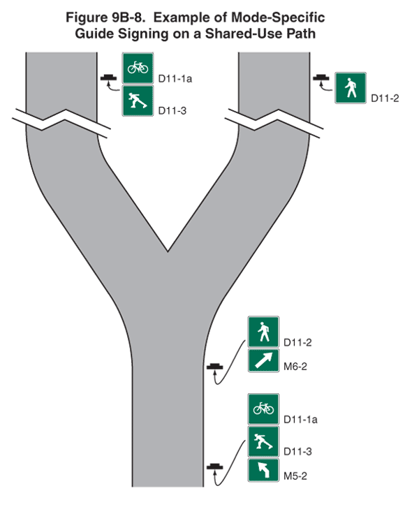
05 Figure 9B-8 shows an example of signing where separate pathways are provided for different non-motorized user types.
Figure 9B-8 Example of Mode-Specific Guide Signing on a Shared-Use Path
Section 9B.26 Object Markers
Option:
01 Fixed objects adjacent to shared-use paths may be marked with Type 1, Type 2, or Type 3 object markers (see Figure 9B-3) such as those described in Section 2C.63. If the object marker is not intended to also be seen by motorists, a smaller version of the Type 3 object marker may be used (see Table 9B-1).
Standard:
02 Obstructions in the traveled way of a shared-use path shall be marked with retroreflectorized material or appropriate object markers.
03 All object markers shall be retroreflective.
04 On Type 3 object markers, the alternating black and retroreflective yellow stripes shall be sloped down at an angle of 45 degrees toward the side on which traffic is to pass the obstruction.
